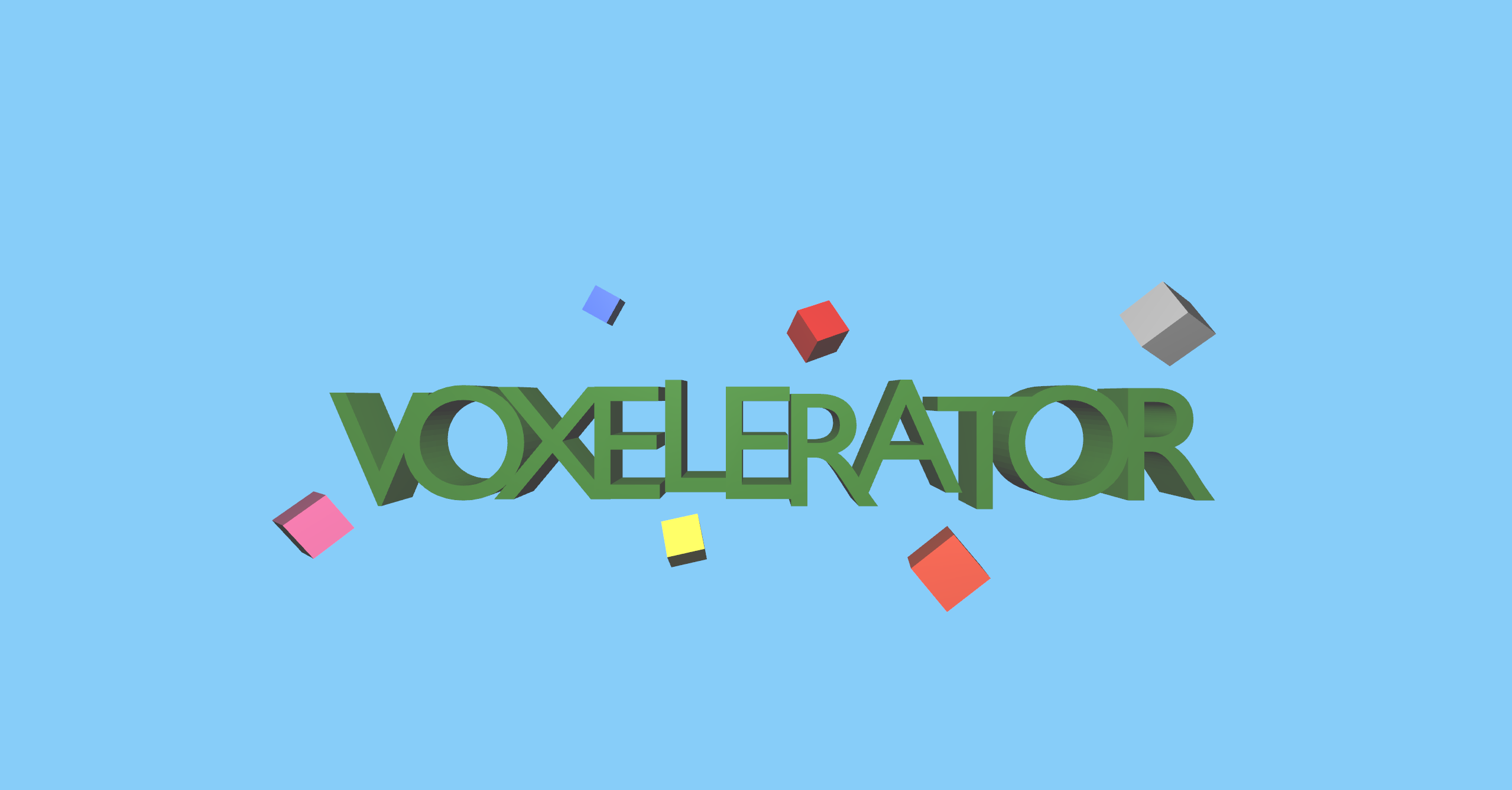
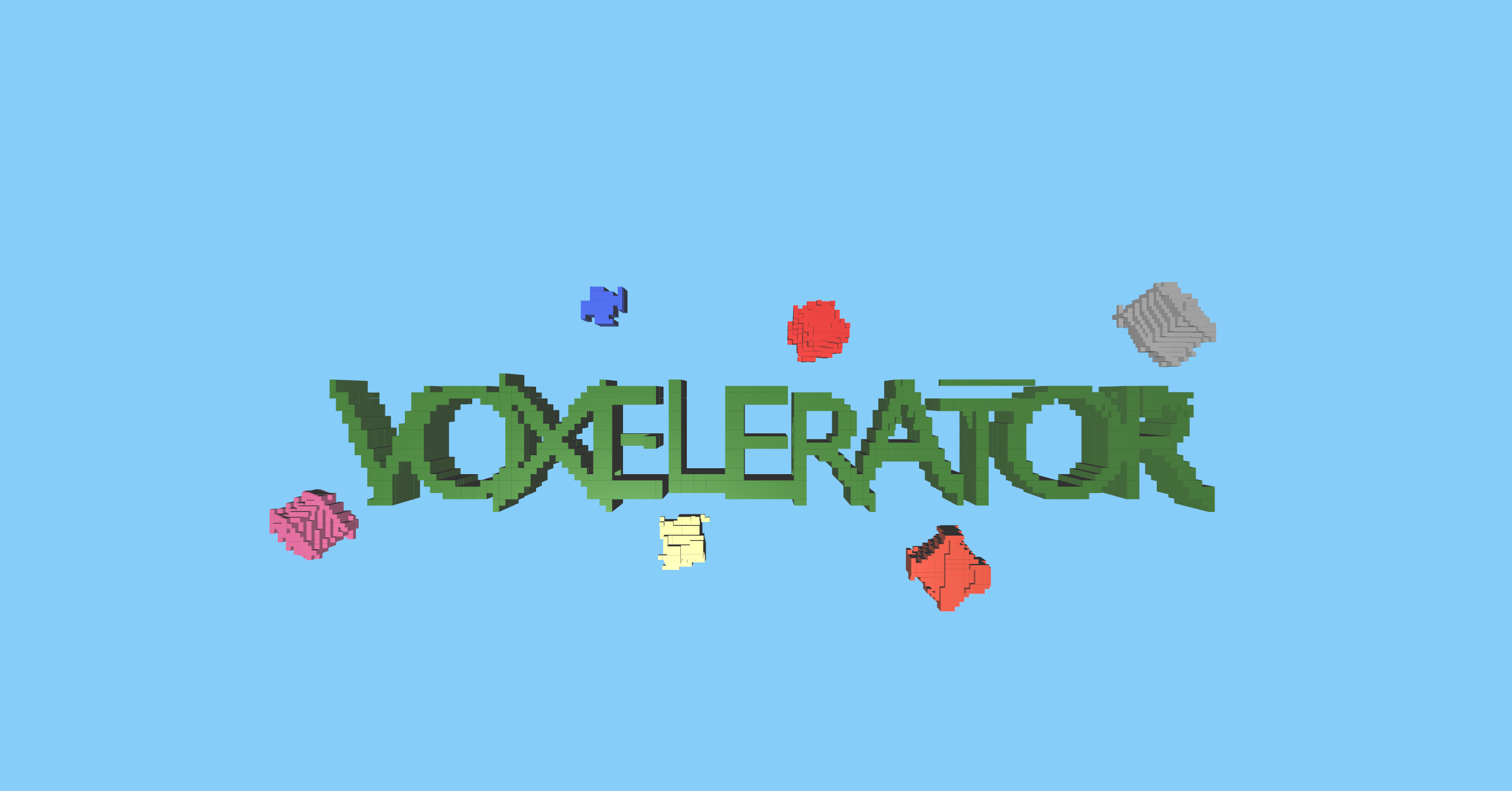


Voxels, short for volumetric pixels represent a value on a regular grid in 3D. They are essentially the 3D equivalents to a pixel in 2D. Each voxel contains volumetric data about a specific point in space, such as color, opacity, texture, or material properties.
Voxels are commonly used in various fields including computer graphics, medical imaging, video games, and scientific visualization.
Voxel-based rendering techniques can offer unique visual styles (Voxel-art) and allow for dynamic environments that can be easily modified in real-time. In this blog, I will talk about how you can turn 3D models into voxel-based model to offer this unique style.
This particular application is done in C++ using openFrameworks but feel free to use the logic with other frameworks or languages. I am using the logic used in the blog Turning 3D Models to Voxel Art with Three.js by Ksenia Kondrashova with a few optimizations.
To use my configurations, download openFrameworks. After downloading, open project generator from the downloaded files and include addons ofxAssimpModelLoader and ofxGui, and then create a project. You can find the documentation of openFrameworks here.
You can find the source code of my project at https://github.com/prathikkaranth/voxelerator. Make sure you have glm built in your project as we will be needing it for the vector math. Openframeworks has it built by default when you create a project. You just have to make sure to include it in your header file.
ofxAssimpModelLoader)The first step would be to extract spatial information such as vertices, edges and faces from the model. There are several ways to do this but I’m going to be using ofxAssimpModelLoader. Alternatively, you can write your own file parser or find other ways like tinyobjloader.
|
|
The nice thing about ofxAssimpModelLoader is that there is a function getMesh() which returns an ofMesh. This is very useful because ofMesh has functions like getIndex() and getVertex() to return vertex and face values.
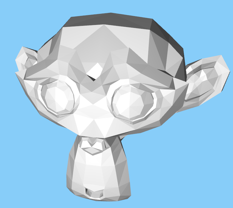
For the purpose of demonstration, we will be using the blender mascot ‘Suzanne’ model.
Now that we know where the faces of the model are, we can spawn a bunch of voxels and check if they lie inside the mesh or not. To do so we need to cast rays in a downward direction from the box and check for ray triangle intersections between the ray and the mesh faces.
We can consider box primitives as voxels or a custom box model. Creating a voxel class and instancing their positions is a good way to handle voxel draw calls.
To do the ray triangle intersections tests, we can use the Möller–Trumbore intersection algorithm - a fast ray triangle intersect algorithm.
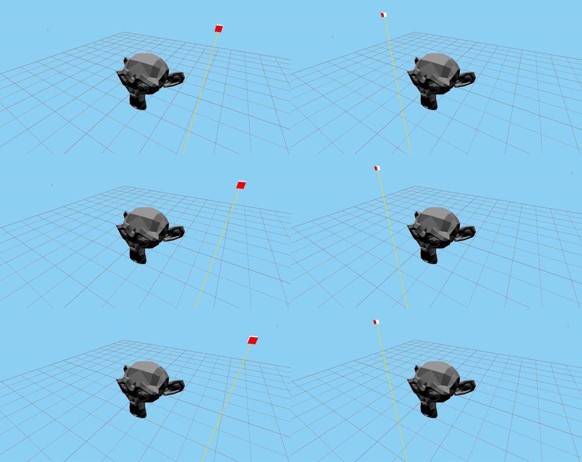
Now that we know if there is an intersection or not, how do we get to know whether a voxel is inside the mesh or not? This can be done by keeping track of the number of intersections. If the intersection count is even, the voxel is outside the mesh. If the intersection count is odd, the voxel is inside the mesh.
|
|
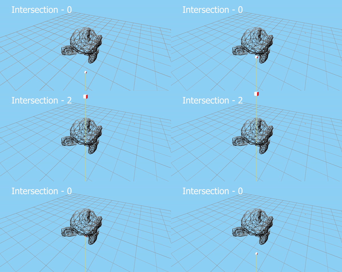
Note that this logic can be applied for closed models only and do not work for planar surfaces or other special geometric models. Most geometric models are closed so this shouldn’t be a problem.
Next step is to spawn the voxels. There are multiple ways to do this but only a few that are optimal. One thing you could try is spawn a bunch of voxels in a grid specifying the bounds of the grid and the grid resolution (number of voxels in the grid). This should work if you know the size of your models and create a grid accordingly but you would have to change those values every time the model changes.
Instead of this, we can create a bounding box for our models. Since we have the mesh data, this should be straightforward. This is useful not only for spawning the voxels but also an optimization which I will discuss later. In order to compute the bounds:
|
|
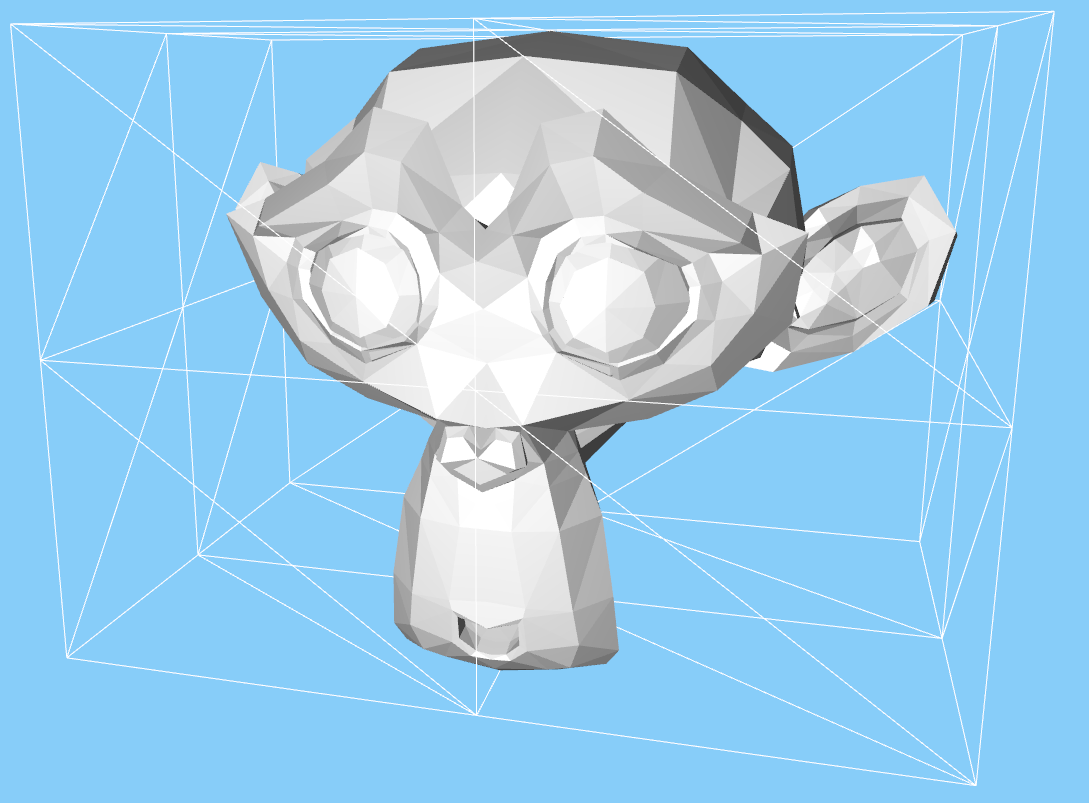
Now that we have a bounding box, we need to fit voxels into that bounding box. We need to adjust the size and spacing between the voxels based on our grid resolution. This is a math problem where you are given a big box and you’re told to fit a bunch of smaller boxes which are all equally sized and spaced in the big box.
|
|
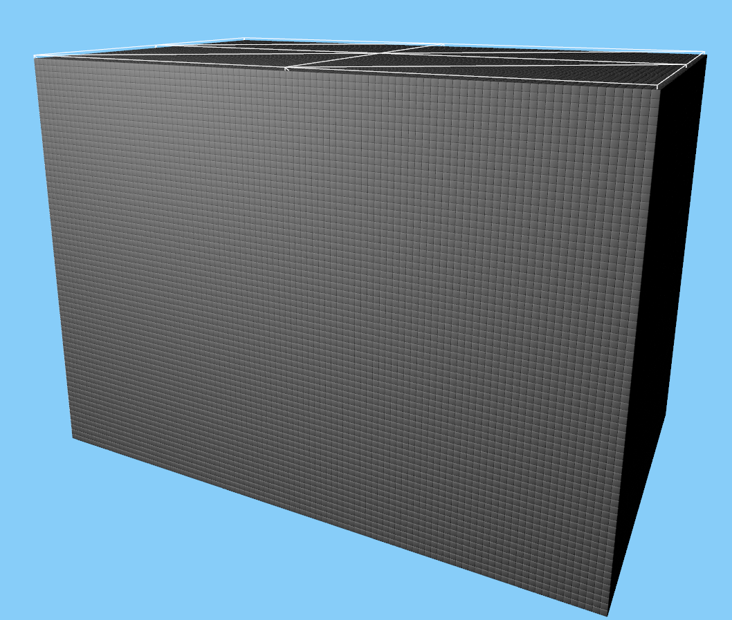
We have the logic to check whether voxels are inside the mesh, and the grid to spawn voxels. The final step is to give a draw call to draw the voxel only if it is inside the mesh.
|
|
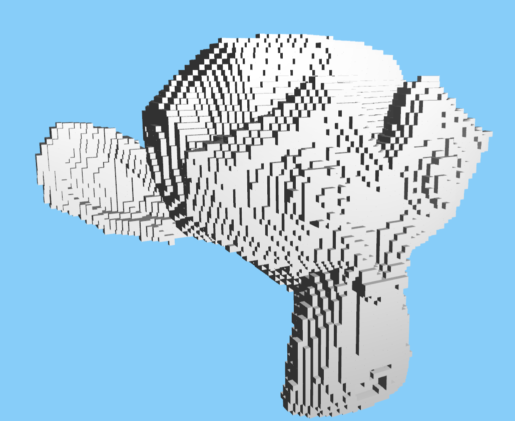
Voilà ✨, Our suzanne is now voxelerated.
We’ve got the main logic working but right now it is a very naive implementation and takes a long time to voxelerate. Realtime render is slow as well due to inefficient draw calls. I will talk about some basic optimizations to increase efficiency and performance.
Many Voxels being drawn inside the mesh are not seen and hence there is no need to draw them. Most renderers are built to handle such cases and is called as frustum culling. Instead of sending all information to your GPU, we will sort visible and invisible elements and render only visible elements. Thanks to this technique, we will earn GPU compute time. OpenFrameworks by default does not use this technique to its full extent and only handles cases where objects are drawn out of the camera’s near and far range.
To handle this case, we need to cast 5 additional rays (6 in total) to your voxels (one on each face) towards its outward face (normal) direction. Then we compute the shortest ray out of the 6 rays that intersect with the mesh (including if inside). If we add a distance threshold, we can limit the number of voxels that spawn inside the mesh.
|
|
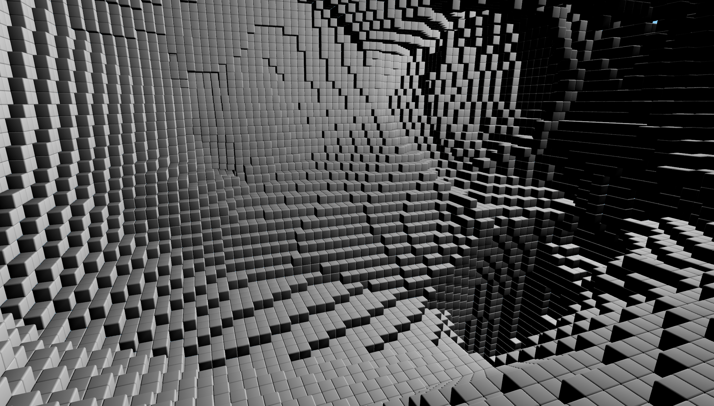
This is how it would look rendering suzanne from inside. All the unnecessary voxels are not drawn.
The get a speedup in voxelerating time, the ray triangle intersection tests can be multithreaded. Since these intersection tests are all asynchronous, this is pretty straightforward. I used std::thread to do some basic parallel processing but I suggest using api’s like OpenMP which is much smarter in handling threads.
If you’ve ever done projects related to ray tracing, you’ve probably heard about BVH or Bounding Volume Hierarchy. BVH’s are accelerated data structures used mainly in ray tracing and collision detection systems to efficiently organize and query geometric objects. The primary purpose of a BVH is to accelerate the process of finding intersections between rays and objects or checking for collisions by reducing the number of comparisons needed. You can find a detailed description of a BVH here. My introduction to BVH’s happened during reading the Ray Tracing in One Weekend books by Peter Shirley. I highly suggest reading them if you’re into ray tracing and computer graphics.
You can take a look at my source code for the bvh implementation which is borrowed from those books. This will result in much faster ray triangle intersects.
These models after voxelerating need to still have materials to look good. In my version, I have been able to add colors for models which have a designated color for a particular mesh. This is done along with the ray hit by also storing the color of the mesh it hits and then assigning that particular voxel that color. This becomes a harder problem to solve when material on the model are applied using UV texturing and something to look upon for further improvements.
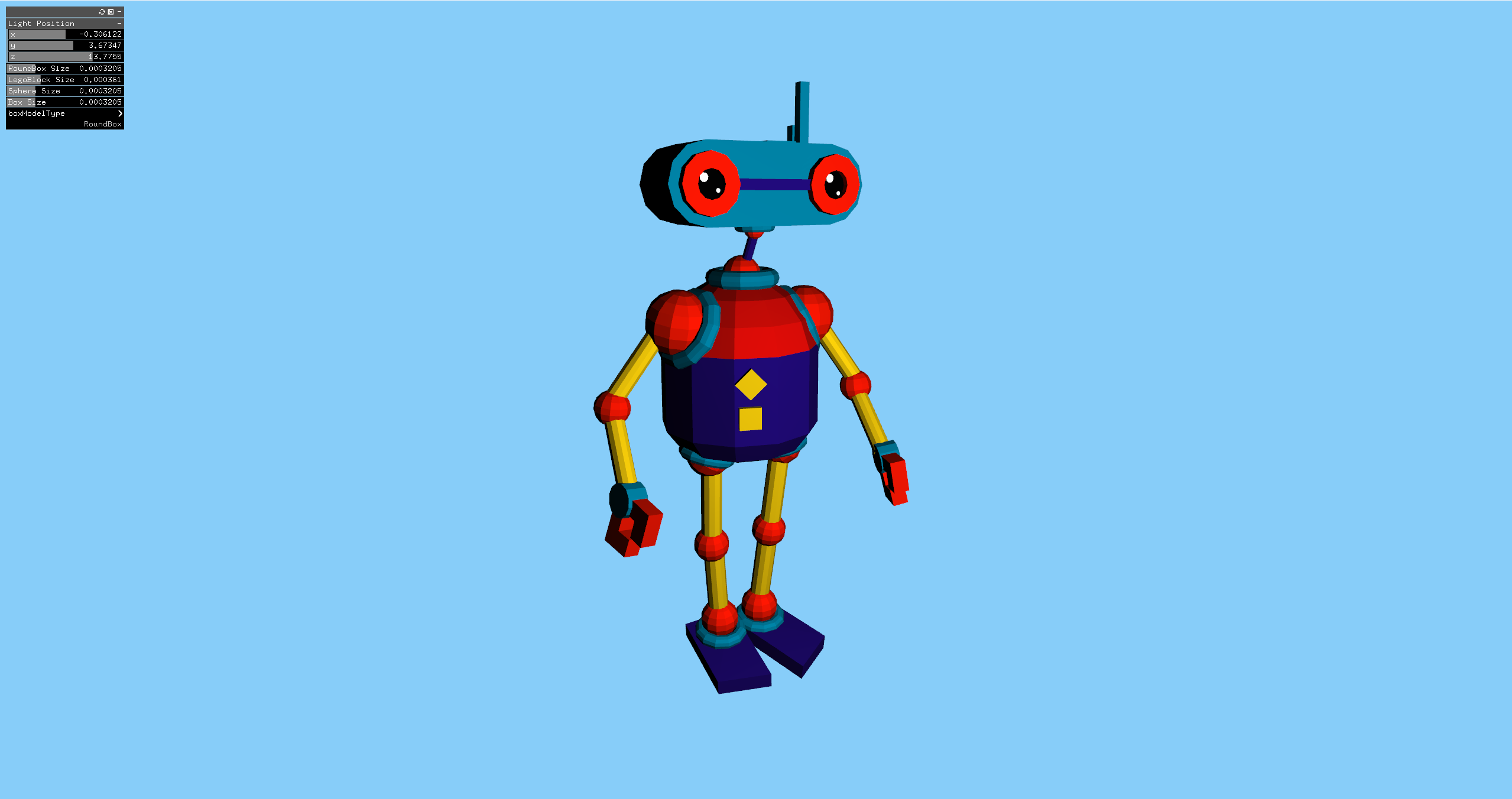
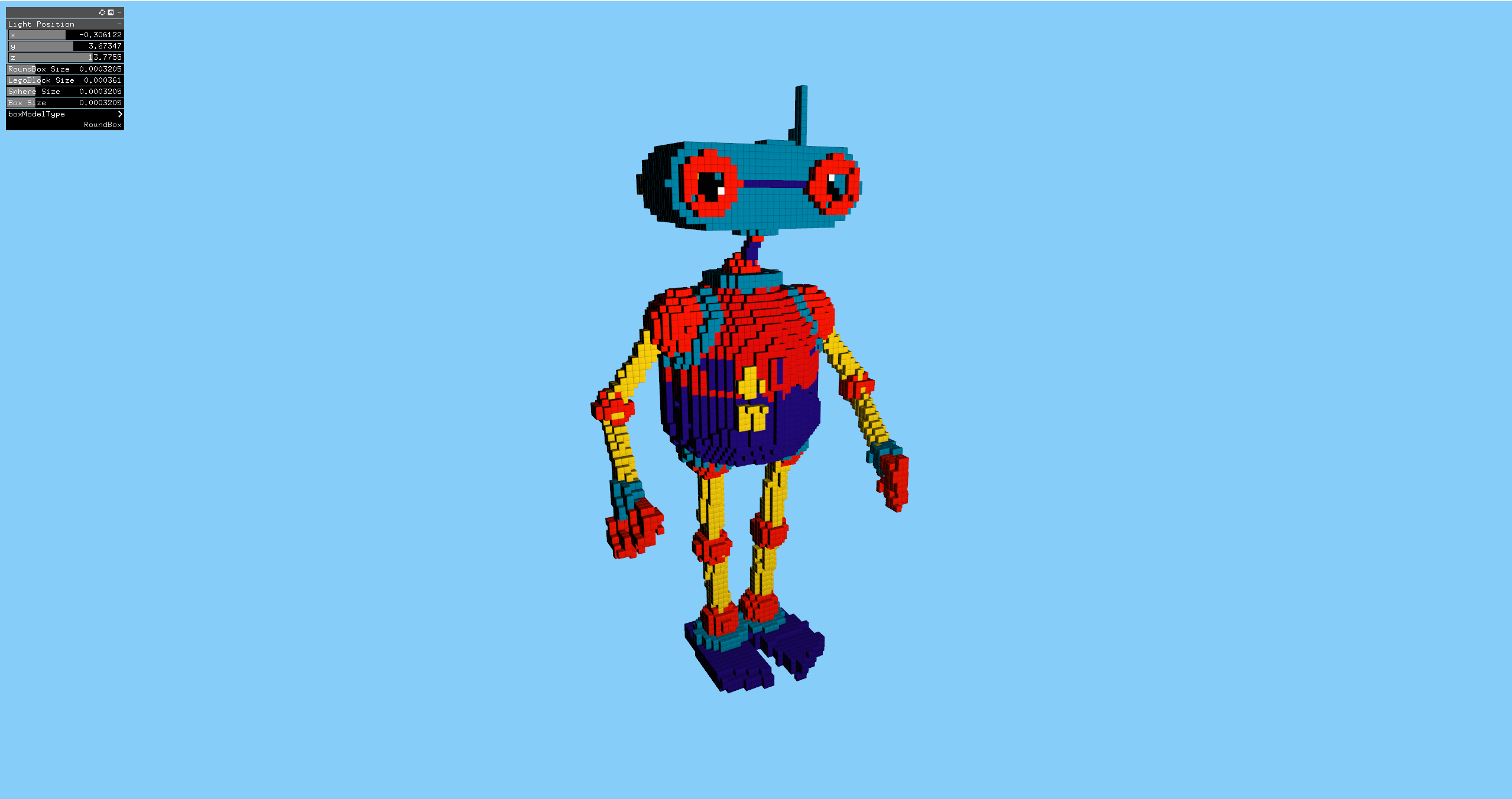
Doodle by jeremy via Poly Pizza
If you notice, the model has separate meshes and each mesh is colored. Hence this works in my implementation.
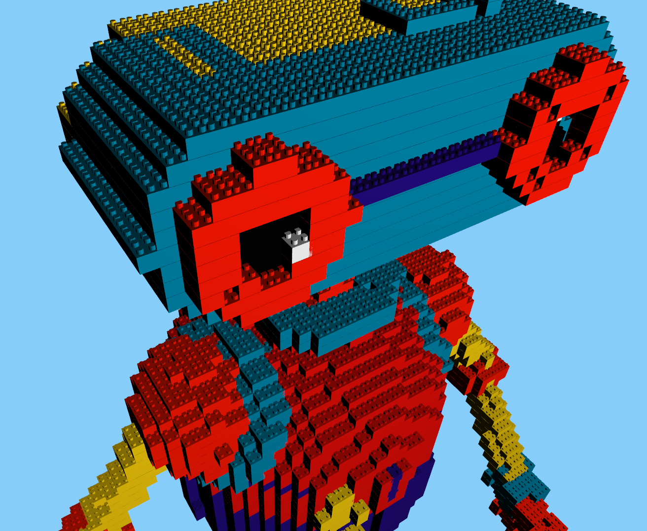
To make it more interesting I have added a lego block model to replace the boxes as voxels.
So thats it for this blog, thanks for reading and hope you were able to build upon this and if you do, please send me your works via email.